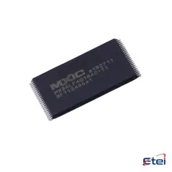
Imagens apenas para referência
74LVC1G79GW
+Lista de MateriaisD FLIP-FLOP, LVC/LCX/Z SERIES, 1
-
FabricanteNXP USA Inc.
-
Peça do Fabricante #74LVC1G79GW
-
Ficha Técnica 74LVC1G79GW DataSheet
-
Em Estoque3800
365 Garantia de Qualidade em 1 dia
7*24 Garantia de serviço em 24 horas
90-Garantia de pós-venda em 1 dia
Garantia de Produto Genuíno
Especificações
| Atributo | Valor |
| Package | Bulk |
| ProductStatus | Active |
Visão Geral
Description
In operation, the flip-flop captures the value of the data input (D) on the rising edge of the clock input (CP) and outputs it at Q. It also includes an asynchronous reset (R) and set (S) inputs, which can be used to immediately reset or set the output state regardless of the clock signal.
The 74LVC1G79GW is widely used in digital circuits for tasks such as data storage, signal synchronization, and data transfer, thanks to its robust performance and compact size, making it ideal for use in space-constrained applications.
Equivalent
1. SN74LVC1G79 from Texas Instruments
2. NXP's 74AUP1G79 - another low-power alternative
3. ON Semiconductor's MC74VHC1G79 - similar functionality with different voltage characteristics
These chips may slightly vary in specifications, so always verify the datasheet for compatibility.
Features
Key features include:
- A wide supply voltage range from 1.65 V to 5.5 V.
- High-speed operation and low power dissipation, suitable for battery-powered devices.
- Over-voltage tolerant inputs, allowing for interfacing with 5 V signals in a 3.3 V system.
- Schmitt-trigger action inputs, providing better noise immunity.
- A small, leadless package option (TSOP or TSSOP) for compact circuit designs.
- Compliance with JEDEC standards for interface compatibility.
The 74LVC1G79GW is typically used in applications requiring temporary data storage and interface between logic circuitry, such as in data buffering, frequency division, or serial-to-parallel data conversion.
Pinout
Here's a quick overview of its pin functions:
1. Pin 1 (OE): Output Enable (active high).
2. Pin 2 (D): Data input.
3. Pin 3 (GND): Ground.
4. Pin 4 (Q): Data output.
5. Pin 5 (CP): Clock input, triggers on the rising edge.
6. Pin 6 (VCC): Supply voltage.
The device operates on a supply voltage range from 1.65 V to 5.5 V, making it suitable for both low-voltage and standard 5 V applications. It is typically used in timing, control, and data storage applications.
Manufacturer
Application
1. Data Storage: Used in registers to store data temporarily.
2. Data Transfer: Facilitates data synchronization between different clock domains.
3. Frequency Division: Can divide frequency in digital circuits.
4. Signal Delay: Used in creating delay circuits for timing adjustments.
5. Counters: Integral in constructing binary counters for digital counting applications.
6. State Machines: Used in the design of finite state machines for controlling processes.
Its low power consumption and high-speed operation make it suitable for portable and high-performance electronics.