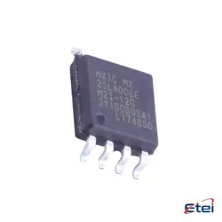
Imagens apenas para referência
CAT24C128WI-GT3
+Lista de MateriaisIC EEPROM 128KBIT I2C 1MHZ 8SOIC
-
Fabricanteonsemi
-
Peça do Fabricante #CAT24C128WI-GT3
-
Pacote SOIC-8
-
Em Estoque2615
365 Garantia de Qualidade em 1 dia
7*24 Garantia de serviço em 24 horas
90-Garantia de pós-venda em 1 dia
Garantia de Produto Genuíno
Especificações
| Atributo | Valor |
| Package / Case | Tape & Reel (TR),Cut Tape (CT),Bulk |
| Part Status | Active |
| Memory Type | Non-Volatile |
| Memory Format | EEPROM |
| Technology | EEPROM |
| Memory Size | 128Kb (16K x 8) |
| Memory Interface | I²C |
| Clock Frequency | 1 MHz |
| Write Cycle Time - Word Page | 5ms |
| Access Time | 400 ns |
| Voltage - Supply | 1.8V ~ 5.5V |
| Operating Temperature | -40°C ~ 85°C (TA) |
| Mounting Type | Surface Mount |
Visão Geral
Description
The EEPROM provides reliable data retention for up to 100 years and supports up to 1 million write/erase cycles, ensuring long-term durability. The CAT24C128WI-GT3 is organized in 16,384 x 8-bit memory cells and supports both random and sequential read operations. With a maximum clock frequency of 1MHz, it facilitates fast data transfer.
The chip is packaged in an 8-pin SOIC (Small Outline Integrated Circuit), enabling compact integration into various electronic designs. Its wide operating temperature range of -40°C to +85°C allows it to function effectively in harsh environments, making it ideal for industrial, automotive, and consumer electronics applications.
Equivalent
Pinout
1. Pin 1 (A0): Device address input. Used to set the least significant bit of the device address.
2. Pin 2 (A1): Device address input. Used to set the second least significant bit of the device address.
3. Pin 3 (A2): Device address input. Used to set the third least significant bit of the device address.
4. Pin 4 (GND): Ground. Connects the device to the system ground.
5. Pin 5 (SDA): Serial Data. Bi-directional data line used for communication with the I2C master.
6. Pin 6 (SCL): Serial Clock. Clock line for synchronizing data transfer with the I2C master.
7. Pin 7 (WP): Write Protect. When connected to VCC, write operations are inhibited.
8. Pin 8 (VCC): Power supply. Typically connected to a positive voltage supply.
This configuration supports standard I2C communication for operations such as reading from and writing to the EEPROM.
Manufacturer
Application
1. Consumer Electronics: Storing configuration settings and user preferences.
2. Industrial Control Systems: Data logging and parameter storage.
3. Medical Devices: Storing calibration data and patient information.
4. Computer Peripherals: Configuration and firmware data storage.
5. Automotive Systems: Retaining settings and diagnostic information.
6. Networking Equipment: Storing MAC addresses and configuration settings.
Its wide operating voltage range and low power consumption make it suitable for battery-powered and low-energy applications.