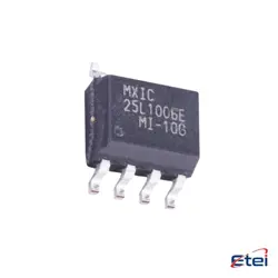
Imagens apenas para referência
LMR14030SDDAR
+Lista de MateriaisIC REG BUCK ADJ 3.5A 8SOPWR
-
FabricanteTexas Instruments
-
Peça do Fabricante #LMR14030SDDAR
-
Pacote HSOIC (DDA)-8
-
Em Estoque5298
365 Garantia de Qualidade em 1 dia
7*24 Garantia de serviço em 24 horas
90-Garantia de pós-venda em 1 dia
Garantia de Produto Genuíno
Especificações
| Atributo | Valor |
| Package | Tape & Reel (TR),Cut Tape (CT) |
| Series | SIMPLE SWITCHER® |
| ProductStatus | Active |
| Function | Step-Down |
| OutputConfiguration | Positive |
| Topology | Buck |
| OutputType | Adjustable |
| NumberofOutputs | 1 |
| Voltage-Input(Min) | 4V |
| Voltage-Input(Max) | 40V |
| Voltage-Output(Min/Fixed) | 0.8V |
| Voltage-Output(Max) | 28V |
| Current-Output | 3.5A |
| Frequency-Switching | 200kHz ~ 2.5MHz |
| SynchronousRectifier | No |
| OperatingTemperature | -40°C ~ 125°C (TJ) |
| MountingType | Surface Mount |
| Package/Case | 8-PowerSOIC (0.154, 3.90mm Width) |
Visão Geral
Description
Equivalent
Features
1. Wide Input Voltage Range: Operates from 4.5V to 40V, making it suitable for various applications, including automotive and industrial.
2. Output Current: Capable of delivering up to 3A of continuous output current.
3. Efficiency: High efficiency, typically over 90%, due to its synchronous rectification feature.
4. Switching Frequency: Fixed 700 kHz switching frequency allows for small external components, reducing overall solution size.
5. Low Quiescent Current: Features a low standby current of 28 µA, enhancing efficiency in light-load conditions.
6. Protection Features: Includes cycle-by-cycle current limit, thermal shutdown, and short circuit protection to ensure reliable operation.
7. Package: Available in a small, thermally enhanced SO PowerPAD package for efficient heat dissipation.
8. Soft Start: Integrated soft-start minimizes inrush current during startup.
These features make the LMR14030SDDAR a versatile choice for efficient power conversion in space-constrained applications.
Pinout
1. VIN: Input voltage supply.
2. SW: Switch node; connects to the inductor.
3. BOOT: Bootstrap capacitor connection for driving the internal high-side MOSFET gate.
4. FB: Feedback pin for output voltage regulation.
5. EN: Enable pin; used to enable or disable the device.
6. GND: Ground connection.
7. PGND: Power ground; provides the return path for the power stage.
8. RT/CLK: Sets the switching frequency or synchronizes to an external clock.
9. SS/TRK: Soft-start or tracking pin; controls the rise time of the output voltage.
10. VCC: Internal LDO output used to power the IC’s internal circuitry.
These pins collectively facilitate the conversion of a higher DC input voltage to a lower DC output voltage with high efficiency, suitable for various power management applications.