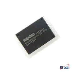
Imagens apenas para referência
NJM4580M-TE1
+Lista de MateriaisNJM4580M-TE1
-
FabricanteNisshinbo Micro Devices Inc.
-
Peça do Fabricante #NJM4580M-TE1
-
Em Estoque5753
365 Garantia de Qualidade em 1 dia
7*24 Garantia de serviço em 24 horas
90-Garantia de pós-venda em 1 dia
Garantia de Produto Genuíno
Especificações
| Atributo | Valor |
| PartStatus | Active |
Visão Geral
Description
The NJM4580M-TE1 is a dual operational amplifier IC produced by New Japan Radio Co., Ltd. It is designed to provide high performance with low noise and distortion, making it suitable for audio applications. The device features a wide bandwidth and fast slew rate, enabling it to handle high-speed signals effectively. The NJM4580M-TE1 operates over a wide range of supply voltages, typically from ±4V to ±18V, which offers flexibility in various circuit designs.
The IC comes in a compact, surface-mountable package, facilitating its integration into modern electronic devices. It is commonly used in audio equipment such as mixers, sound processors, and preamplifiers due to its ability to maintain signal integrity. Additionally, the NJM4580M-TE1's low total harmonic distortion characteristics ensure high-fidelity sound reproduction. Its robust design also includes internal frequency compensation, enhancing its stability across various operating conditions. Overall, the NJM4580M-TE1 is a reliable choice for applications requiring precise audio amplification.
The IC comes in a compact, surface-mountable package, facilitating its integration into modern electronic devices. It is commonly used in audio equipment such as mixers, sound processors, and preamplifiers due to its ability to maintain signal integrity. Additionally, the NJM4580M-TE1's low total harmonic distortion characteristics ensure high-fidelity sound reproduction. Its robust design also includes internal frequency compensation, enhancing its stability across various operating conditions. Overall, the NJM4580M-TE1 is a reliable choice for applications requiring precise audio amplification.
Equivalent
The NJM4580M-TE1 is a dual operational amplifier commonly used in audio applications. Equivalent products include the Texas Instruments RC4580, the JRC NJM4580D, and the ON Semiconductor MC33078. These alternatives offer similar performance characteristics, such as low noise, high gain, and low distortion, making them suitable replacements in circuits where the NJM4580M-TE1 is used. Always verify the specific requirements of your application to ensure compatibility.
Features
The NJM4580M-TE1 is a dual operational amplifier designed for high-performance audio applications. Key features include:
- Low Noise and Distortion: It offers low noise and distortion, making it suitable for high-fidelity audio applications.
- High Slew Rate: The amplifier has a high slew rate of approximately 5V/µs, which helps in improving transient response.
- Wide Bandwidth: It provides a wide gain bandwidth product, enhancing its performance in various audio frequency applications.
- Low Power Consumption: The NJM4580M-TE1 is designed to consume low power, increasing efficiency.
- Dual Amplifier Configuration: It contains two independent operational amplifiers in a single package.
- Versatile Package: Available in a compact surface-mount package, making it suitable for space-limited designs.
- Wide Supply Voltage Range: It operates over a wide range of supply voltages, increasing its applicability in different circuits.
These features make the NJM4580M-TE1 ideal for audio preamplifiers, mixers, and other sound-related electronic applications.
- Low Noise and Distortion: It offers low noise and distortion, making it suitable for high-fidelity audio applications.
- High Slew Rate: The amplifier has a high slew rate of approximately 5V/µs, which helps in improving transient response.
- Wide Bandwidth: It provides a wide gain bandwidth product, enhancing its performance in various audio frequency applications.
- Low Power Consumption: The NJM4580M-TE1 is designed to consume low power, increasing efficiency.
- Dual Amplifier Configuration: It contains two independent operational amplifiers in a single package.
- Versatile Package: Available in a compact surface-mount package, making it suitable for space-limited designs.
- Wide Supply Voltage Range: It operates over a wide range of supply voltages, increasing its applicability in different circuits.
These features make the NJM4580M-TE1 ideal for audio preamplifiers, mixers, and other sound-related electronic applications.
Pinout
The NJM4580M-TE1 is a dual operational amplifier. It comes in an 8-pin package and is designed for applications requiring low noise and high output drive capability. Here's a brief overview of the pin functions:
1. Pin 1 (Output A): The output terminal for the first operational amplifier.
2. Pin 2 (Inverting Input A): The inverting input for the first operational amplifier.
3. Pin 3 (Non-Inverting Input A): The non-inverting input for the first operational amplifier.
4. Pin 4 (V- / Ground): The negative power supply terminal or ground.
5. Pin 5 (Non-Inverting Input B): The non-inverting input for the second operational amplifier.
6. Pin 6 (Inverting Input B): The inverting input for the second operational amplifier.
7. Pin 7 (Output B): The output terminal for the second operational amplifier.
8. Pin 8 (V+ / Supply Voltage): The positive power supply terminal.
This op-amp is commonly used in audio equipment and other precision applications due to its high performance.
1. Pin 1 (Output A): The output terminal for the first operational amplifier.
2. Pin 2 (Inverting Input A): The inverting input for the first operational amplifier.
3. Pin 3 (Non-Inverting Input A): The non-inverting input for the first operational amplifier.
4. Pin 4 (V- / Ground): The negative power supply terminal or ground.
5. Pin 5 (Non-Inverting Input B): The non-inverting input for the second operational amplifier.
6. Pin 6 (Inverting Input B): The inverting input for the second operational amplifier.
7. Pin 7 (Output B): The output terminal for the second operational amplifier.
8. Pin 8 (V+ / Supply Voltage): The positive power supply terminal.
This op-amp is commonly used in audio equipment and other precision applications due to its high performance.
Manufacturer
The NJM4580M-TE1 is manufactured by New Japan Radio Co., Ltd. (NJR), which is a Japanese company known for producing a wide range of electronic components and semiconductor products. NJR specializes in the design and manufacture of analog and digital integrated circuits, microwave devices, and other semiconductor products used in various applications such as consumer electronics, automotive, industrial, and telecommunications. The company has a strong reputation for developing reliable and high-performance components that are utilized in a broad spectrum of electronic devices globally.
Application
The NJM4580M-TE1 is a dual operational amplifier commonly used in audio applications. Its low noise and high output drive capabilities make it suitable for audio preamplifiers, equalizers, and active filters. It is also utilized in consumer audio electronics, professional audio equipment, and other precision analog circuits where high performance is required. Additionally, the NJM4580M-TE1 can be applied in instrumentation and sensor signal conditioning, thanks to its low distortion and wide bandwidth.
Package
The NJM4580M-TE1 is a dual operational amplifier packaged in an 8-pin DMP (Dual inline Miniature Package) type. This package is suitable for various applications requiring compact size and efficient thermal performance.