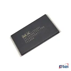
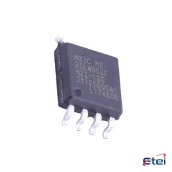
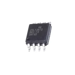
Imagens apenas para referência
SN74HC574PWR
+Lista de MateriaisIC FF D-TYPE SNGL 8BIT 20TSSOP
-
FabricanteTexas Instruments
-
Peça do Fabricante #SN74HC574PWR
-
Pacote TSSOP-20
-
Em Estoque1512
365 Garantia de Qualidade em 1 dia
7*24 Garantia de serviço em 24 horas
90-Garantia de pós-venda em 1 dia
Garantia de Produto Genuíno
Especificações
| Atributo | Valor |
| Package | Tape & Reel (TR),Cut Tape (CT),Bulk |
| Series | 74HC |
| ProductStatus | Active |
| Function | Standard |
| Type | D-Type |
| OutputType | Tri-State, Non-Inverted |
| NumberofElements | 1 |
| NumberofBitsperElement | 8 |
| ClockFrequency | 40 MHz |
| MaxPropagationDelay@VMaxCL | 31ns @ 6V, 50pF |
| TriggerType | Positive Edge |
| Current-OutputHighLow | 7.8mA, 7.8mA |
| Voltage-Supply | 2V ~ 6V |
| Current-Quiescent(Iq) | 8 µA |
| InputCapacitance | 3 pF |
| OperatingTemperature | -40°C ~ 85°C (TA) |
| MountingType | Surface Mount |
| SupplierDevicePackage | 20-TSSOP |
Visão Geral
Description
The SN74HC574PWR is packaged in a TSSOP (Thin Shrink Small Outline Package) configuration, making it suitable for space-constrained applications. This device is particularly useful in buffering and latching data in bus-oriented systems or other data-processing applications.
Key features include a clock (CP) input, which captures the input data on the rising edge, and an output enable (OE) input, which controls the state of the outputs. When OE is low, the outputs display the stored data; when OE is high, outputs are in a high-impedance state. This flexibility makes it ideal for use in a variety of digital systems needing stable data storage and retrieval.
Equivalent
Features
1. High-Speed Operation: Operates at a wide supply voltage range (2V to 6V) with typical propagation delays.
2. Low Power Consumption: Consumes minimal power due to the CMOS technology.
3. 3-State Outputs: Allows multiple devices to connect to the same bus, enabling output control via an output enable pin.
4. Latch-Up Performance: Exhibits excellent latch-up immunity, typically greater than 200 mA.
5. Input Clamping Diodes: Protects against static discharge and voltage spikes.
6. Wide Temperature Range: Functions efficiently over a temperature range of -40°C to 85°C, suitable for various applications.
7. Standard Pin Configuration: Compatible with industry-standard footprints for ease of design and integration.
8. Reliability: Manufactured with high reliability, ensuring consistent performance in various environments.
These features make it suitable for buffer, latch, and storage applications in digital systems.
Pinout
1. Pins 1-8 (D0-D7): Data inputs for each of the 8 flip-flops.
2. Pin 9 (GND): Ground connection.
3. Pin 10 (OE̅): Output Enable, active low. Controls the 3-state outputs.
4. Pins 11-18 (Q0-Q7): 3-state outputs corresponding to the data inputs.
5. Pin 19 (CLK): Clock input. Data is transferred to the outputs on the rising edge of the clock signal.
6. Pin 20 (VCC): Positive supply voltage.
The device is used in applications where temporary data storage is required, allowing data to be latched with a clock signal and selectively output. The 3-state capability enables multiple devices to share the same output lines.
Manufacturer
Application
1. Data Storage and Transfer: It is used for temporary storage of data in digital circuits, enabling data transfer between microprocessors and peripheral components.
2. Signal Latching and Buffering: The device acts as a latch, capturing and holding data for stability in high-speed digital systems.
3. Digital Logic Design: It is employed in creating complex logic circuits, aiding in sequential logic operations.
4. Microcontroller Interfacing: The flip-flop is used to interface with microcontrollers, managing and synchronizing data flow.
5. Clocked Operations: Utilized in synchronous systems requiring clocked data handling.
These applications make it versatile for various electronic and embedded system designs.