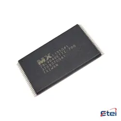
Imagens apenas para referência
SN74LV4051APWR
+Lista de MateriaisIC MUX/DEMUX 8X1 16TSSOP
-
FabricanteTexas Instruments
-
Peça do Fabricante #SN74LV4051APWR
-
Pacote TSSOP-16
-
Em Estoque7172
365 Garantia de Qualidade em 1 dia
7*24 Garantia de serviço em 24 horas
90-Garantia de pós-venda em 1 dia
Garantia de Produto Genuíno
Especificações
| Atributo | Valor |
| Package | Tape & Reel (TR),Cut Tape (CT) |
| ProductStatus | Active |
| Multiplexer/DemultiplexerCircuit | 8:1 |
| NumberofCircuits | 1 |
| On-StateResistance(Max) | 75Ohm |
| Channel-to-ChannelMatching(ΔRon) | 1.3Ohm |
| Voltage-SupplySingle(V+) | 2V ~ 5.5V |
| SwitchTime(TonToff)(Max) | 14ns, 14ns |
| -3dbBandwidth | 35MHz |
| ChannelCapacitance(CS(off)CD(off)) | 0.5pF, 23.4pF |
| Current-Leakage(IS(off))(Max) | 100nA |
| OperatingTemperature | -40°C ~ 85°C (TA) |
| MountingType | Surface Mount |
| Package/Case | 16-TSSOP (0.173, 4.40mm Width) |
Visão Geral
Description
Key features include a wide operating voltage range from 2V to 5.5V, making it suitable for both 3.3V and 5V systems. The device supports both digital and analog signals, with a bandwidth suitable for audio and some RF applications. It offers low on-resistance and low propagation delay, ensuring minimal signal distortion.
The SN74LV4051APWR is housed in a TSSOP package, which is compact and suitable for space-constrained applications. It is commonly used in data acquisition systems, communication systems, and any application requiring signal routing or switching. The device also includes ESD protection and latch-up immunity, enhancing its reliability in various operating environments.
Equivalent
1. CD4051 from Texas Instruments or ON Semiconductor
2. 74HC4051 from NXP or STMicroelectronics
3. MC14051 from ON Semiconductor
4. HEF4051 from NXP
These alternatives generally offer similar functionality with variations in voltage ranges and switching speeds. Always consult datasheets for compatibility with your specific application requirements.
Features
1. Voltage Range: Operates over a wide voltage range from 2 V to 5.5 V.
2. High Bandwidth: Supports high-speed signal switching.
3. Low Power Consumption: Consumes minimal power, making it suitable for battery-operated devices.
4. Low ON-Resistance: Provides low on-state resistance, ensuring minimal signal distortion.
5. 3-State Outputs: Facilitates interfacing with multiple signals without interference.
6. Channel Selection: Utilizes 3-bit binary address pins to select one of the eight available channels.
7. Wide Compatibility: Compatible with standard CMOS logic levels.
8. Temperature Range: Operates reliably over a wide temperature range from -40°C to 125°C.
9. Package: Available in a TSSOP package for space-efficient designs.
These features make the SN74LV4051APWR suitable for a variety of applications, including data acquisition systems, signal routing, and audio/video signal multiplexing.
Pinout
Here's a brief outline of its pin functions:
- Pins 1-3 (A, B, C): These are the address select inputs. They are used to select which I/O channel is connected to the common I/O terminal.
- Pin 4 (EN or INH): This is the enable or inhibit input. When this pin is high, the device is disabled, and all channels are turned off.
- Pins 5-12 (Y0-Y7): These are the multiplexer/demultiplexer channels.
- Pin 13 (Z): This is the common I/O terminal.
- Pins 14 (VCC): This is the power supply pin.
- Pin 15 (GND): This is the ground pin.
- Pin 16 (NC): Typically not connected, can be used for other purposes if specified by the manufacturer.
This configuration allows the device to select one of eight inputs or outputs to be connected to a common terminal, making it versatile for various routing applications.