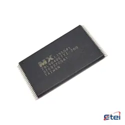
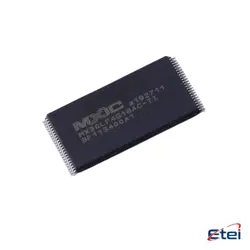
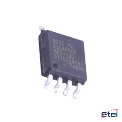
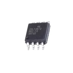
Imagens apenas para referência
TLC5615IDR
+Lista de MateriaisIC DAC 10BIT V-OUT 8SOIC
-
FabricanteTexas Instruments
-
Peça do Fabricante #TLC5615IDR
-
Pacote 8-SOIC
-
Em Estoque2393
365 Garantia de Qualidade em 1 dia
7*24 Garantia de serviço em 24 horas
90-Garantia de pós-venda em 1 dia
Garantia de Produto Genuíno
Especificações
| Atributo | Valor |
| Package | Tape & Reel (TR),Cut Tape (CT) |
| ProductStatus | Active |
| NumberofBits | 10 |
| NumberofD/AConverters | 1 |
| SettlingTime | 12.5µs (Typ) |
| OutputType | Voltage - Buffered |
| DifferentialOutput | No |
| DataInterface | SPI |
| ReferenceType | External |
| Voltage-SupplyAnalog | 5V |
| Voltage-SupplyDigital | 5V |
| INL/DNL(LSB) | ±1 (Max), ±0.1 |
| Architecture | String DAC |
| OperatingTemperature | -40°C ~ 85°C |
| Package/Case | 8-SOIC (0.154, 3.90mm Width) |
| SupplierDevicePackage | 8-SOIC |
Visão Geral
Description
The TLC5615IDR features a simple, 3-wire serial interface compatible with standard SPI, QSPI, and Microwire protocols, simplifying integration with microcontrollers and DSPs. The DAC provides a fast settling time of 10 microseconds, suitable for dynamic signal processing tasks.
The device is housed in a small, surface-mount SOIC package (marked by the "IDR" in its name), making it ideal for space-constrained designs. It also includes a power-down mode to reduce power consumption further when the DAC is not in use.
Typical applications include digital control systems, waveform generation, and signal reconstruction. The TLC5615IDR is valued for its precision, reliability, and ease of use in various electronic applications.
Equivalent
1. MCP4901 from Microchip Technology
2. AD7304 from Analog Devices
3. DAC7512 from Texas Instruments
4. MAX522 from Maxim Integrated
These alternatives offer similar functionality with varying specifications such as resolution, interface type, and package options. Always verify compatibility and performance requirements before selecting a substitute.
Features
Pinout
Here is a concise breakdown of the pin functions:
1. VDD (Pin 1): Power supply pin for the device.
2. OUT (Pin 2): Analog output voltage from the DAC.
3. REF (Pin 3): Reference voltage input. The output voltage range is determined by this reference voltage.
4. GND (Pin 4): Ground pin for the device.
5. DIN (Pin 5): Serial data input. Used for inputting the digital code that will be converted to an analog output.
6. SCLK (Pin 6): Serial clock input. Controls the timing of the data input through DIN.
7. CS (Pin 7): Chip select input. Enables the data shift into the input register when low.
8. NC (Pin 8): No connection. Not internally connected.
The device communicates via a simple serial interface and is suitable for various applications like waveform generation and control systems.